Normally these builts are mainly for display during events or competition, which I have no choice but to prepare them to be powered by dry batteries; as the organizer would not have approve me using their live wire. However, after the event, usually I ll just take off the batteries for i find the short battery life span and changing of batteries is really not my favorite part.
Hence the idea of converting it into something which i can power it by using a DC converter. With that, I can switch them on anytime without have to leave the battery in it n fear of battery leakage.
In fact, it is pretty simple.
Here I am using a toy UFO Grabber as an example.

First, unscrew and open the bottom of the kit, where all the wires n circuit board are.

Dont be afraid of the wires and such. It might looks like there r a lot of stuff, but look carefully, it is pretty straight forward: there is one red wire from the positive of the battery box line to the on/off switch. Another black wire out from the negative. (just ignore the green wire from negative to the switch, it is just a ground wire)
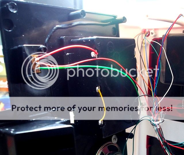
From battery positive: Red

From battery negative: Black wire

On/off switch, one red wire from battery's positive goes in here, and another red wire goes out to the motor and other parts of the kit, to power them. The on/off switch is just to connect & cut off the red wire.

So, what I am going to do is just connect a DC convertor to it to replace the batteries. that's it. simple as that.
I use this kind of multiple voltage DC converter. It comes with switches for various voltage and even positive/negative. Looking at the original number of battery used, which is 3, (1.5V x 3 =4,5V) I tweak it to 4.5V. Besides that, it also comes with multiple (female) jack.
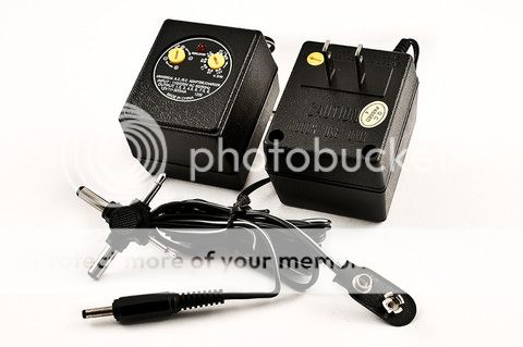
This is the first type of male connector.
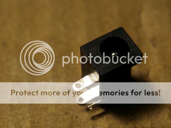
Ok, it fits well.
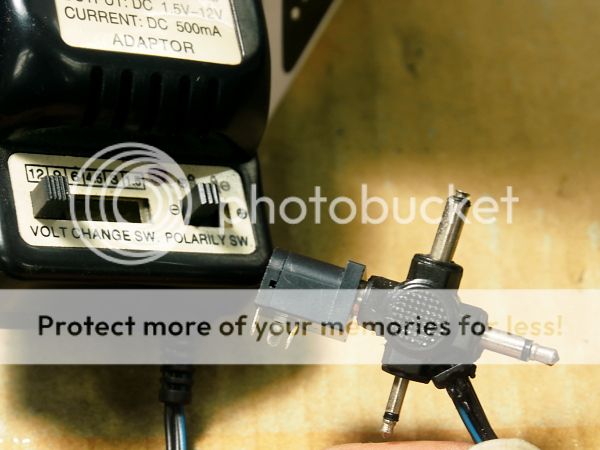
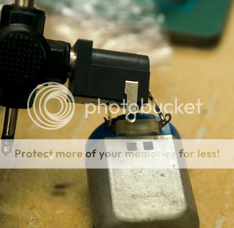
This is to test whether there s current going thru. Besides that, u can oso use a LED to test the positive n negative. Just make sure you turn the voltage to 3.0v or lesser.
Now, draw the shape onto the exact place where i want to put the connector.

Drill multiple holes, then cut the plastic out.

Ok now secure the connector onto the kit. I use epoxy glue at the back and some pla strip at the front: to cover up any imperfection of the hole i made, and to make the connector more secure.

This is another type. This will be slightly easier as it is round, and it has a ring screw at the back to help secure the connector to the kit. Reapeat the procedure of testing n connecting wires.

Drill a hole, then use a reamer to enlarge the hole.

Like this:

Example: done.

The third type. This is even easier. It comes with connector by screwing the wire tight. So there is no soldering needed at all.


Done. Simple as that.

The fourth type.

It needs soldering, as u can see after open up, there's a positive n negative point. However, as compared to the 3rd type, the wires are well hidden and it looks a lot more tidier.


The good thing about the last 2 types is u only need to use pin vise to drill a small hole, as large as the diameter of the wire would do.


Ready to connect

Although there r altogether 3 connectors, and 6 wires, all the 3 reds i connect them into one red. while black i do the same thing. Pardon me for the lousy tape used. Just for photography purpose for this wip sharing.
At last the 2 wires goes to the positive n negative point of the battery casing.

Overall view. This is due to i m doing this introduction to various connector. Normally u just need to make one connector.
With this, i do not have to install batteries but just connect it to a DC converter and whenever I need to switch it one, it will be just very easy.


Just a little noob sharing. :)

No comments:
Post a Comment